2022-11-12
Dehumidifier Hack
I hate lights in my room while I sleep and we’ve got a couple appliances that love to give some feedback that they are on.

Although it’s not that bright, it still annoys the shit out of me so at some point I got the bright idea that I could probably swap out the leds with similar diode. I popped the top off and with the help of some solder wick and 2 1N4148 diodes, the design flaw was corrected.
Here’s the board with one of the swapped diodes and an original led.

And with all leds swapped out.

Pure bliss.

2022-09-30
The AVR Toolchain
One of the goals I had when I started getting into the digital side of electronics was to get a good grasp of the GNU toolchain and some of the avr tools. The arduino platform is nice but it doesn’t really give you a good grasp of what’s actually happening so here’s a primer from an attiny perspective and some of the common tools used to understand what’s in the final binary.
There’s already a great overview of the main avr toolchain), but this article provides some examples built against a simple binary to wrap your head around it all.
Tools
All of these examples are build with the attiny25 family in mind and uses a binary from a really dumb program in , loop.c:
int main(void) {
    int i = 0;
    while(i < 10000) {
        i++;
    }
}
This was compiled to the loop binary using avr-gcc -g -mmcu=avr25 -o loop loop.c
-gto add debugging symbols, gives an easier time linking back to the individual line of code.-mmcu=avr25specifies the AVR instruction set architecture to use. Change this to whatever chip you’re targeting.
At a high level, avr-libc provides a standard c library that can be compiled with gcc. The tools here are mostly provided through binutils and you would normally use make to stitch it all together.
Objdump
This is the swiss army knife to picking apart object files. Typically used to take a look at the disassembly:
> avr-objdump -m avr25 -S loop

loop:     file format elf32-avr

Disassembly of section .text:

00000000 <main>:
int main(void) {
   0:	cf 93       	push	r28
   2:	df 93       	push	r29
   4:	00 d0       	rcall	.+0      	; 0x6 <L0^A>

00000006 <L0^A>:
   6:	cd b7       	in	r28, 0x3d	; 61
   8:	de b7       	in	r29, 0x3e	; 62

0000000a <.Loc.1>:
    int i = 0;
   a:	1a 82       	std	Y+2, r1	; 0x02
   c:	19 82       	std	Y+1, r1	; 0x01

0000000e <.Loc.2>:
    while(i < 10000) {
   e:	05 c0       	rjmp	.+10     	; 0x1a <.L2>

00000010 <.L3>:
        i++;
  10:	89 81       	ldd	r24, Y+1	; 0x01
  12:	9a 81       	ldd	r25, Y+2	; 0x02
  14:	01 96       	adiw	r24, 0x01	; 1
  16:	9a 83       	std	Y+2, r25	; 0x02
  18:	89 83       	std	Y+1, r24	; 0x01

0000001a <.L2>:
    while(i < 10000) {
  1a:	89 81       	ldd	r24, Y+1	; 0x01
  1c:	9a 81       	ldd	r25, Y+2	; 0x02
  1e:	80 31       	cpi	r24, 0x10	; 16
  20:	97 42       	sbci	r25, 0x27	; 39
  22:	b4 f3       	brlt	.-20     	; 0x10 <.L3>
  24:	80 e0       	ldi	r24, 0x00	; 0
  26:	90 e0       	ldi	r25, 0x00	; 0

00000028 <.Loc.5>:
    }
  28:	0f 90       	pop	r0
  2a:	0f 90       	pop	r0
  2c:	df 91       	pop	r29
  2e:	cf 91       	pop	r28
  30:	08 95       	ret
The -S flag attempts to intermix the original source code along with the assembly.
The output of this dump is a little confusing at first but let’s break it down. Looking at the counter increment code:
# This is the address in the elf file and the associated debugging symbol <.L3>
00000010 <.L3>:

# We're looking at the increment instruction here
        i++;

# 10 is the address, 89 81 is the actual data.
# objdump translates this to ldd	r24, Y+1 for an attiny.
  10:	89 81       	ldd	r24, Y+1	; 0x01
  12:	9a 81       	ldd	r25, Y+2	; 0x02
  14:	01 96       	adiw	r24, 0x01	; 1
  16:	9a 83       	std	Y+2, r25	; 0x02
  18:	89 83       	std	Y+1, r24	; 0x01
Hexdump
Probably not that useful but shows a raw view of the file.
1 byte per line dump:
> hexdump -v -e '1/1 "%02x " "\n"' loop
7f
45
4c
46
01
01
01
... a lot more is dumped
Od - Octal Dump
Way simpler to use than hexdump.
No address: -An and just text: -a.
> od -An -a loop
del   E   L   F soh soh soh nul nul nul nul nul nul nul nul nul
stx nul   S nul soh nul nul nul nul nul nul nul   4 nul nul nul
84  bs nul nul  em nul nul nul   4 nul  sp nul stx nul   ( nul
cr nul  ff nul soh nul nul nul   t nul nul nul nul nul nul nul
... once again, lots more dumped
Size
Easy way to see the sizes of each section.
> avr-size --format=SysV loop
loop  :
section          size      addr
.text              50         0
.data               0   8388704
.comment           36         0
.debug_aranges     32         0
.debug_info        85         0
.debug_abbrev      78         0
.debug_line        91         0
.debug_frame       52         0
.debug_str         95         0
Total             519
Objcopy
Elf files contain a bunch of unnecessary sections that would be a waste to store in our limited flash space on the target, like all the debugging sections and comments. This command is similar to strip but also encodes the file from elf to various formats.
Intel hex
Most microcontrollers code uploads use an ihex file format rather than an elf file.
Building ihex from an elf:
> avr-objcopy -j .text -j .data -O ihex loop loop.hex && cat loop.hex
:10000000CF93DF9300D0CDB7DEB71A82198205C037
:1000100089819A8101969A83898389819A81803125
:100020009742B4F380E090E00F900F90DF91CF9172
:02003000089531
:00000001FF
Binary
You can take a look at the raw binary if hex is annoying to look at. Not that this is really useful outside of educational purposes.
# first dump to a binary file
> avr-objcopy -O binary --only-section=.text main test.bin

# Now display the binary for one instruction per line, `xxd` can handle the conversion:
> xxd -b -c 2 test.bin
00000000: 00001110 11000000  ..
00000002: 00010101 11000000  ..
00000004: 00010100 11000000  ..
00000006: 00010011 11000000  ..
00000008: 00010010 11000000  ..
0000000a: 00010001 11000000  ..
0000000c: 00010000 11000000  ..
0000000e: 00001111 11000000  ..
00000010: 00001110 11000000  ..
00000012: 00001101 11000000  ..
00000014: 00001100 11000000  ..
00000016: 00001011 11000000  ..
00000018: 00001010 11000000  ..
0000001a: 00001001 11000000  ..
0000001c: 00001000 11000000  ..
0000001e: 00010001 00100100  .$
00000020: 00011111 10111110  ..
00000022: 11001111 11100101  ..
00000024: 11010010 11100000  ..
00000026: 11011110 10111111  ..
00000028: 11001101 10111111  ..
0000002a: 00000010 11010000  ..
0000002c: 00000100 11000000  ..
0000002e: 11101000 11001111  ..
00000030: 10010000 11100000  ..
00000032: 10000000 11100000  ..
00000034: 00001000 10010101  ..
00000036: 11111000 10010100  ..
00000038: 11111111 11001111  ..
AVR GCC
This is the main compiler I use when working with avr chips.
Standards
C has published new standard for the language over time. New standards bring new features or datatypes. For an example of one I like, c99 introduced boolean datatypes. There are a number of different standards, as of 2022 theres c89, gnu89, c94, c99, gnu99, c11, gnu11, c17, gnu17, c2x, and gnu2x. I’m not sure why each release has a GNU equivalent or the history behind that, but there are differences, mostly a couple keywords and macros.
Note use gnu* standards for arduino, I’ve seen some cases in the SpencerKonde ATtiny core where the asm keyword is used.
Linking
The avr-gcc compiler not only has many AVR ISAs compilation support, it also provides the linker with defaults. This means that the architecture flag -m needs to always be specified.
For AVRs, the interrupt table starts at 0x000. Dumping the table for an attiny85, compiled with -mmcu=attiny85:
> avr-objdump -S  -m avr25 loop
...
00000000 <__vectors>:
   0:	0e c0       	rjmp	.+28     	; 0x1e <__ctors_end>
   2:	15 c0       	rjmp	.+42     	; 0x2e <__bad_interrupt>
   4:	14 c0       	rjmp	.+40     	; 0x2e <__bad_interrupt>
   6:	13 c0       	rjmp	.+38     	; 0x2e <__bad_interrupt>
   8:	12 c0       	rjmp	.+36     	; 0x2e <__bad_interrupt>
   a:	11 c0       	rjmp	.+34     	; 0x2e <__bad_interrupt>
   c:	10 c0       	rjmp	.+32     	; 0x2e <__bad_interrupt>
   e:	0f c0       	rjmp	.+30     	; 0x2e <__bad_interrupt>
  10:	0e c0       	rjmp	.+28     	; 0x2e <__bad_interrupt>
  12:	0d c0       	rjmp	.+26     	; 0x2e <__bad_interrupt>
  14:	0c c0       	rjmp	.+24     	; 0x2e <__bad_interrupt>
  16:	0b c0       	rjmp	.+22     	; 0x2e <__bad_interrupt>
  18:	0a c0       	rjmp	.+20     	; 0x2e <__bad_interrupt>
  1a:	09 c0       	rjmp	.+18     	; 0x2e <__bad_interrupt>
  1c:	08 c0       	rjmp	.+16     	; 0x2e <__bad_interrupt>
Compare this to the Arduino Uno’s ATmega328p, compiled with -mmcu=atmega328p:
> avr-objdump -S  -m avr5 loop
...
00000000 <__vectors>:
   0:	0c 94 34 00 	jmp	0x68	; 0x68 <__ctors_end>
   4:	0c 94 3e 00 	jmp	0x7c	; 0x7c <__bad_interrupt>
   8:	0c 94 3e 00 	jmp	0x7c	; 0x7c <__bad_interrupt>
   c:	0c 94 3e 00 	jmp	0x7c	; 0x7c <__bad_interrupt>
  10:	0c 94 3e 00 	jmp	0x7c	; 0x7c <__bad_interrupt>
  14:	0c 94 3e 00 	jmp	0x7c	; 0x7c <__bad_interrupt>
  18:	0c 94 3e 00 	jmp	0x7c	; 0x7c <__bad_interrupt>
  1c:	0c 94 3e 00 	jmp	0x7c	; 0x7c <__bad_interrupt>
  20:	0c 94 3e 00 	jmp	0x7c	; 0x7c <__bad_interrupt>
  24:	0c 94 3e 00 	jmp	0x7c	; 0x7c <__bad_interrupt>
  28:	0c 94 3e 00 	jmp	0x7c	; 0x7c <__bad_interrupt>
  2c:	0c 94 3e 00 	jmp	0x7c	; 0x7c <__bad_interrupt>
  30:	0c 94 3e 00 	jmp	0x7c	; 0x7c <__bad_interrupt>
  34:	0c 94 3e 00 	jmp	0x7c	; 0x7c <__bad_interrupt>
  38:	0c 94 3e 00 	jmp	0x7c	; 0x7c <__bad_interrupt>
  3c:	0c 94 3e 00 	jmp	0x7c	; 0x7c <__bad_interrupt>
  40:	0c 94 3e 00 	jmp	0x7c	; 0x7c <__bad_interrupt>
  44:	0c 94 3e 00 	jmp	0x7c	; 0x7c <__bad_interrupt>
  48:	0c 94 3e 00 	jmp	0x7c	; 0x7c <__bad_interrupt>
  4c:	0c 94 3e 00 	jmp	0x7c	; 0x7c <__bad_interrupt>
  50:	0c 94 3e 00 	jmp	0x7c	; 0x7c <__bad_interrupt>
  54:	0c 94 3e 00 	jmp	0x7c	; 0x7c <__bad_interrupt>
  58:	0c 94 3e 00 	jmp	0x7c	; 0x7c <__bad_interrupt>
  5c:	0c 94 3e 00 	jmp	0x7c	; 0x7c <__bad_interrupt>
  60:	0c 94 3e 00 	jmp	0x7c	; 0x7c <__bad_interrupt>
  64:	0c 94 3e 00 	jmp	0x7c	; 0x7c <__bad_interrupt>
Avrdude
Pretty slick tool to read and write memory on your avr chip.
The Arduino platform has a pretty good integration with these tools. I found it to be helpful to turn the ide verbosity up to read the avrdude commands that are run. There’s a config file that comes from whatever core you are using that might be useful.
The following examples are based on an attiny85 connected to a Sparkfun tinyIsp programmer plugged into a usb port.
Upload an ihex file:
# -U [memory(flash/eeprom)]:[w/r]:[input/output file]:[i stands for intel hex]
avrdude -v -c usbtiny -B8 -p attiny85 -U flash:w:hello.hex:i
Dump the flash:
avrdude -v -c usbtiny -B8 -p attiny85 -U flash:r:dump.hex:i
avr-objdump -sSd -m avr25 dump.hex
Terminal mode to dump part of eeprom:
avrdude -v -c usbtiny -B8 -p attiny85 -t
>>> dump eeprom 0 16

Reading | ################################################## | 100% 0.02s

0000  ff ff ff ff ff ff ff ff  ff ff ff ff ff ff ff ff  |................|
Changing the clock speed from 8Mhz internal to 1Mhz internal. Note that the F_CPU macro in your code needs to match the fuse value. Use a fuse calculator for these. Setting the fuses:
avrdude -v -c usbtiny -B8 -p attiny85 -t
>>> dump lfuse

Reading | ################################################## | 100% 0.00s

0000  e2                                                |.               |

>>> write lfuse 0 0x62

Info: Writing 1 bytes starting from address 0x00

Writing | ################################################## | 100% 0.01s

>>> read lfuse

Reading | ################################################## | 100% 0.00s

0000  62                                                |b               |
2022-08-10
GCC Optimization Levels
Optimization levels are really weird.
Using the function and compiling for an attiny85, ie --mmcu=attiny85.
int main(void) {
    int i = 0;
    while(i < 10000) {
        i++;
    }
}
We can disassemble with avr-objdump -sS -m avr25 led. As a disclaimer, I’m not pretending I know what any of this means.
Using -Os ie optimize for code side, it looks like the entire function is optimized away!
> avr-objdump -sS -m avr25 led
...
00000030 <main>:
{
    int i = 0;
    while(i < 10000) {
        i++;
    }
}
  30:	90 e0       	ldi	r25, 0x00	; 0
  32:	80 e0       	ldi	r24, 0x00	; 0
  34:	08 95       	ret
And by comparison, using -O0, fastest compile time and the gcc default:
00000030 <main>:
// #include "wait.h"

int main(void) {
  30:	cf 93       	push	r28
  32:	df 93       	push	r29
  34:	00 d0       	rcall	.+0      	; 0x36 <L0^A>

00000036 <L0^A>:
  36:	cd b7       	in	r28, 0x3d	; 61
  38:	de b7       	in	r29, 0x3e	; 62

0000003a <.Loc.1>:
    int i = 0;
  3a:	1a 82       	std	Y+2, r1	; 0x02
  3c:	19 82       	std	Y+1, r1	; 0x01

0000003e <.Loc.2>:
    while(i < 10000) {
  3e:	05 c0       	rjmp	.+10     	; 0x4a <.L2>

00000040 <.L3>:
        i++;
  40:	89 81       	ldd	r24, Y+1	; 0x01
  42:	9a 81       	ldd	r25, Y+2	; 0x02
  44:	01 96       	adiw	r24, 0x01	; 1
  46:	9a 83       	std	Y+2, r25	; 0x02
  48:	89 83       	std	Y+1, r24	; 0x01

0000004a <.L2>:
    while(i < 10000) {
  4a:	89 81       	ldd	r24, Y+1	; 0x01
  4c:	9a 81       	ldd	r25, Y+2	; 0x02
  4e:	80 31       	cpi	r24, 0x10	; 16
  50:	97 42       	sbci	r25, 0x27	; 39
  52:	b4 f3       	brlt	.-20     	; 0x40 <.L3>
  54:	80 e0       	ldi	r24, 0x00	; 0
  56:	90 e0       	ldi	r25, 0x00	; 0

00000058 <.Loc.5>:
    }
}
  58:	0f 90       	pop	r0
  5a:	0f 90       	pop	r0
  5c:	df 91       	pop	r29
  5e:	cf 91       	pop	r28
  60:	08 95       	ret
With -O1:
00000030 <main>:
// #include "wait.h"

int main(void) {
  30:	80 e1       	ldi	r24, 0x10	; 16
  32:	97 e2       	ldi	r25, 0x27	; 39

00000034 <.L2>:
    int i = 0;
    while(i < 10000) {
  34:	01 97       	sbiw	r24, 0x01	; 1

00000036 <.LVL2>:
  36:	f1 f7       	brne	.-4      	; 0x34 <.L2>

00000038 <.Loc.8>:
        i++;
    }
}
  38:	90 e0       	ldi	r25, 0x00	; 0
  3a:	80 e0       	ldi	r24, 0x00	; 0

0000003c <.LVL3>:
  3c:	08 95       	ret
And finally with -O2 and -O3 we are back to optimizing everything away:
00000030 <main>:
int main(void) {
    int i = 0;
    while(i < 10000) {
        i++;
    }
}
  30:	90 e0       	ldi	r25, 0x00	; 0
  32:	80 e0       	ldi	r24, 0x00	; 0
  34:	08 95       	ret
So I guess the TLDR here is try and test them all?
The case where the entire function is optimized away seems funny to me, what if you hand rolled a sleep with a big loop? Wouldn’t that be grand if it just disappeared?
2022-07-21
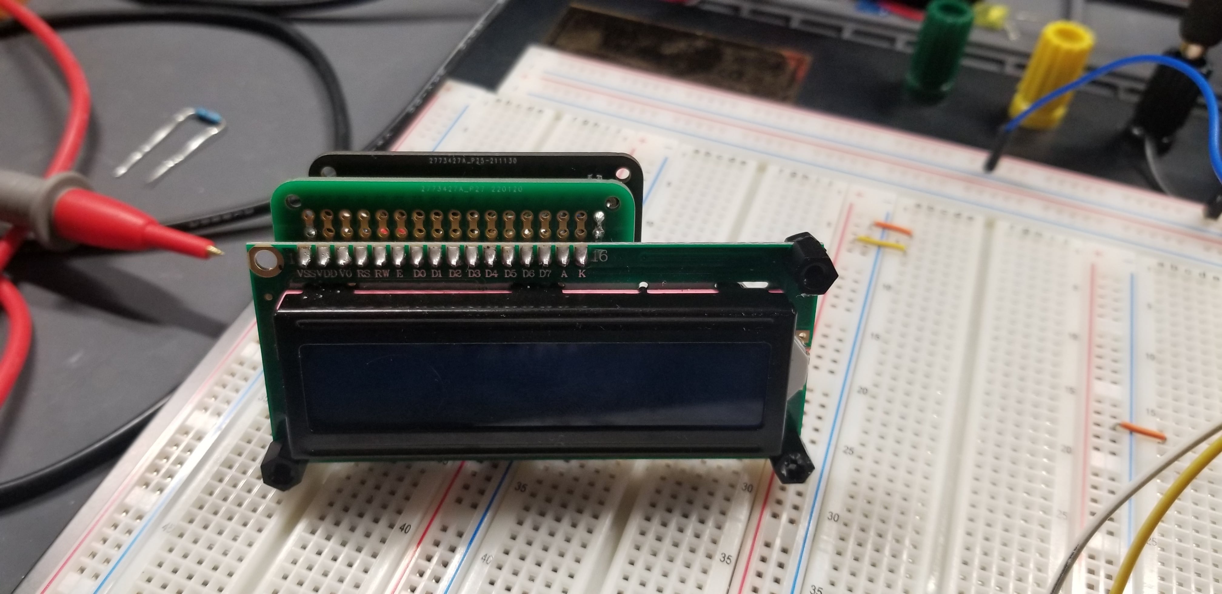
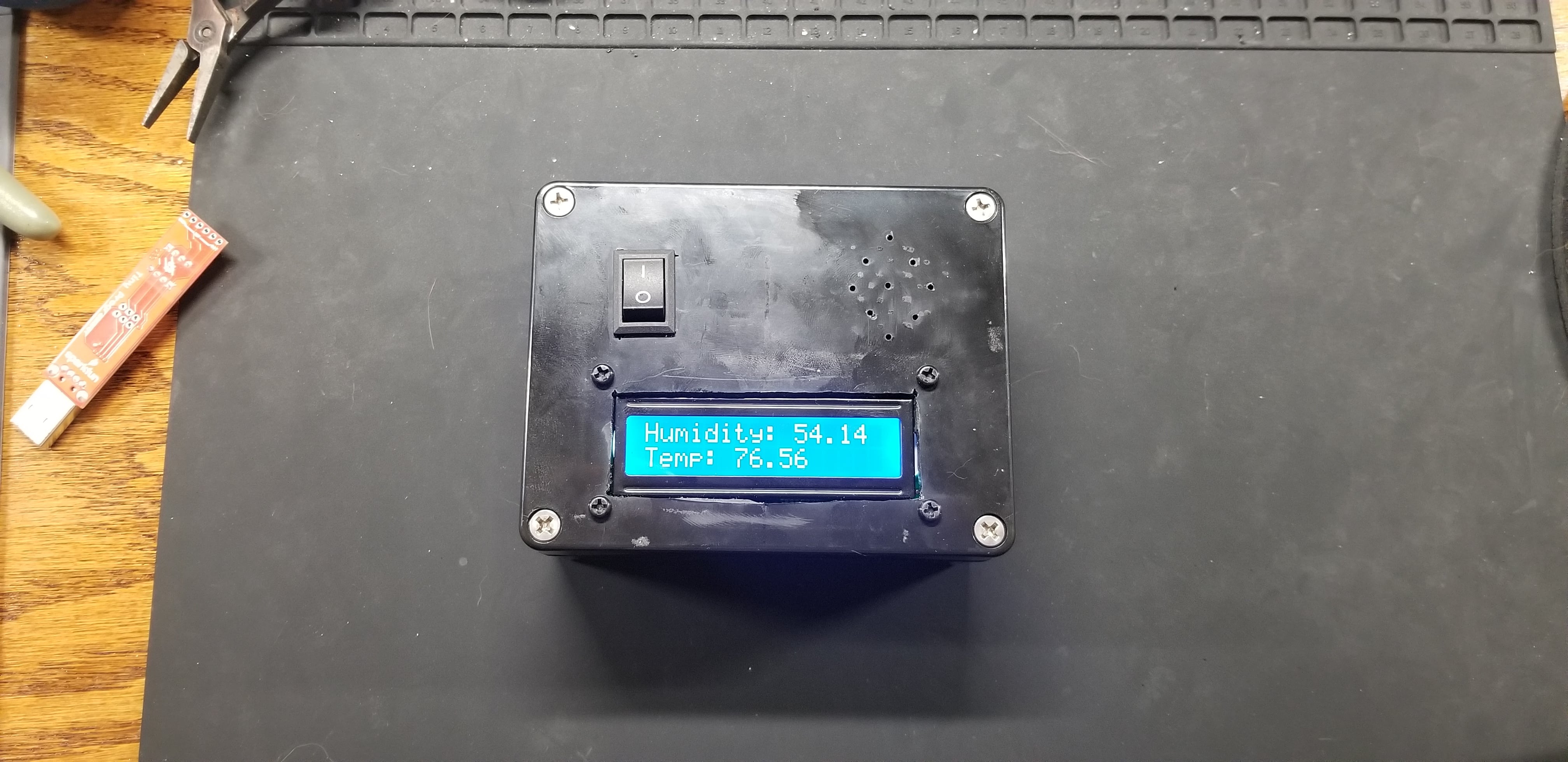
Thermometer
Why buy a $10 thermometer when you can spend $100 and build one yourself in 15-20 hours?
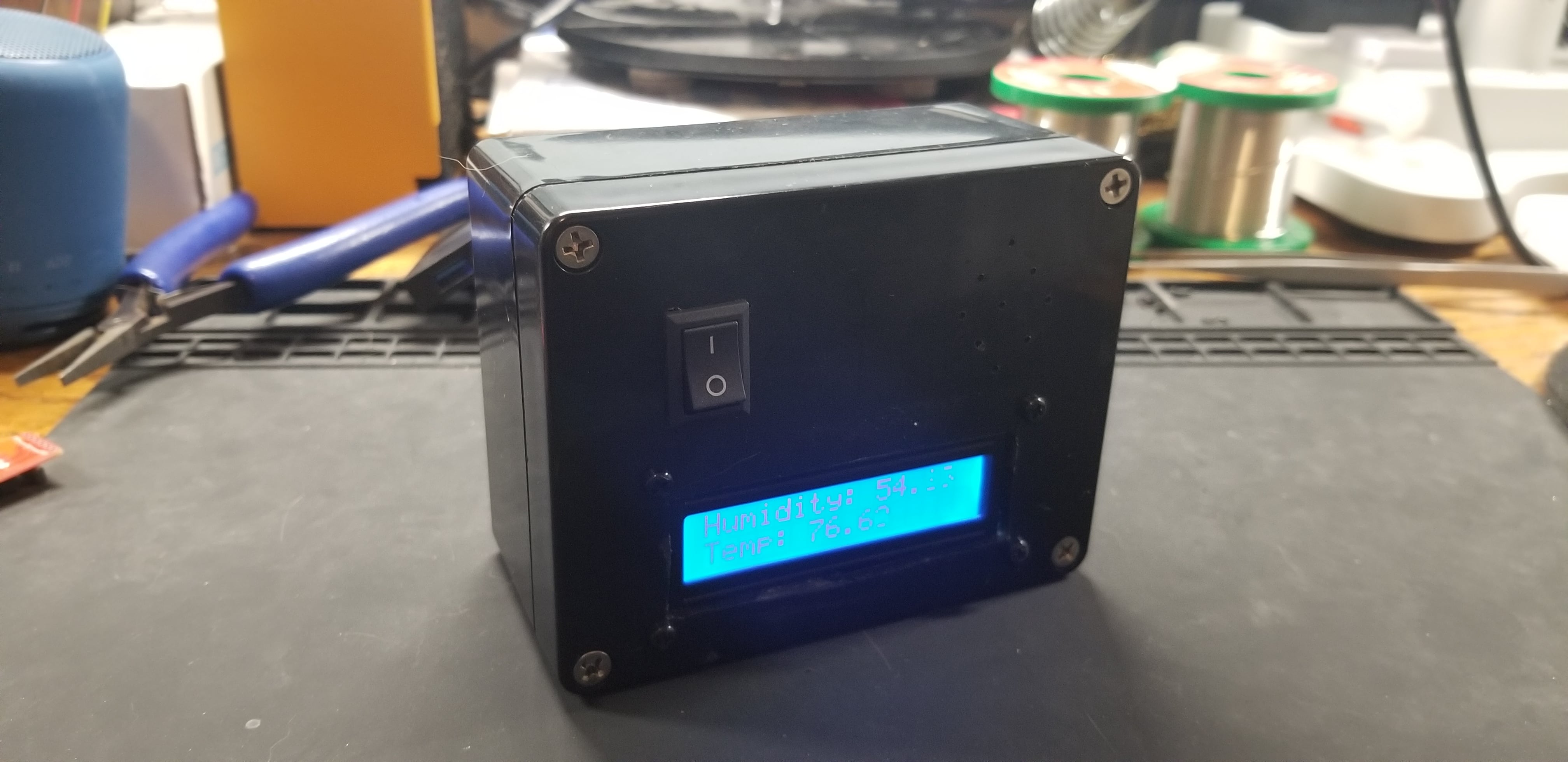
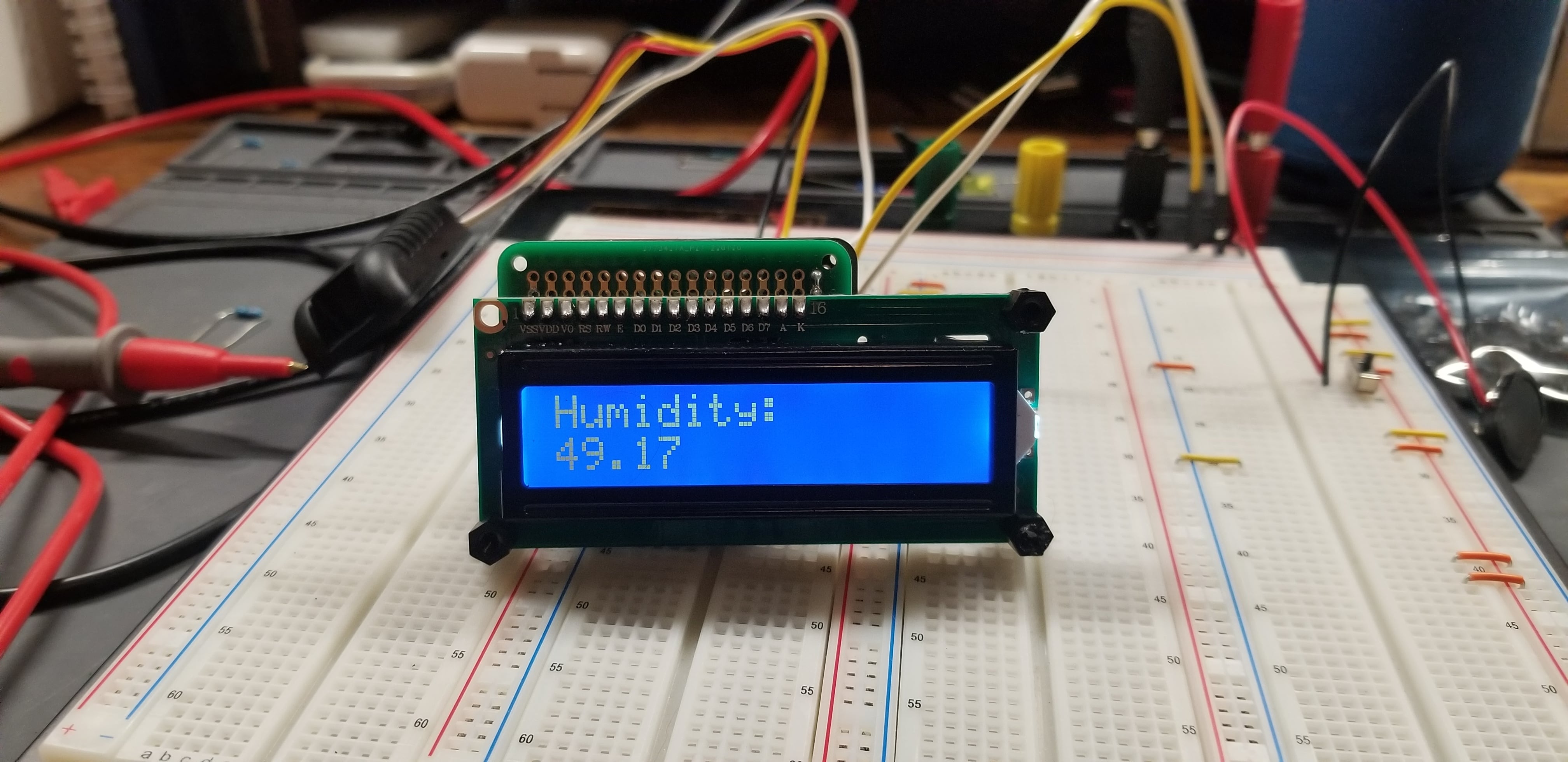
Caitlin kept saying the thermostat was off so I build this to find out. As a bonus, it also tells me my house is too humid so now I have to also figure that out. Fun.
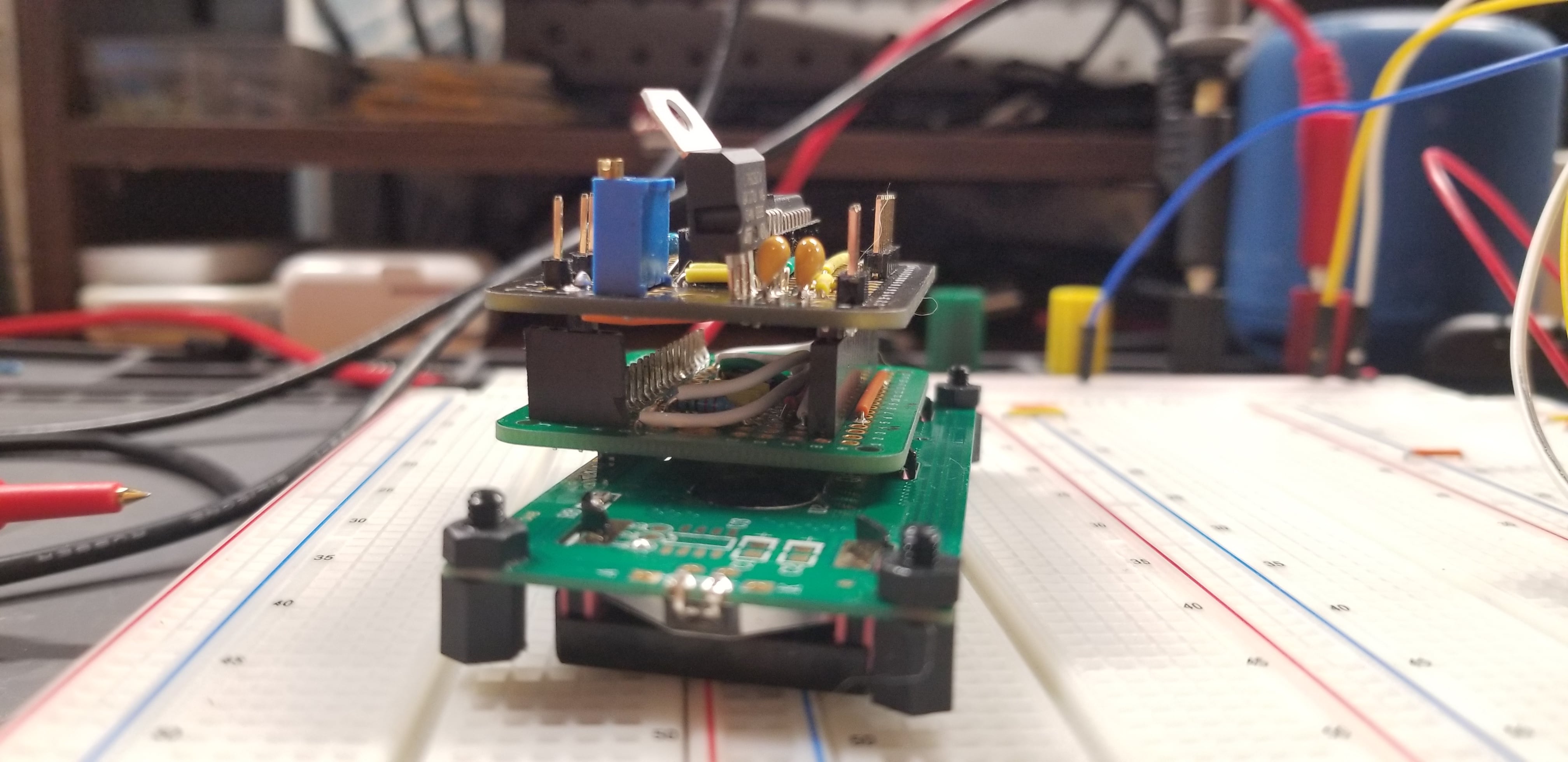
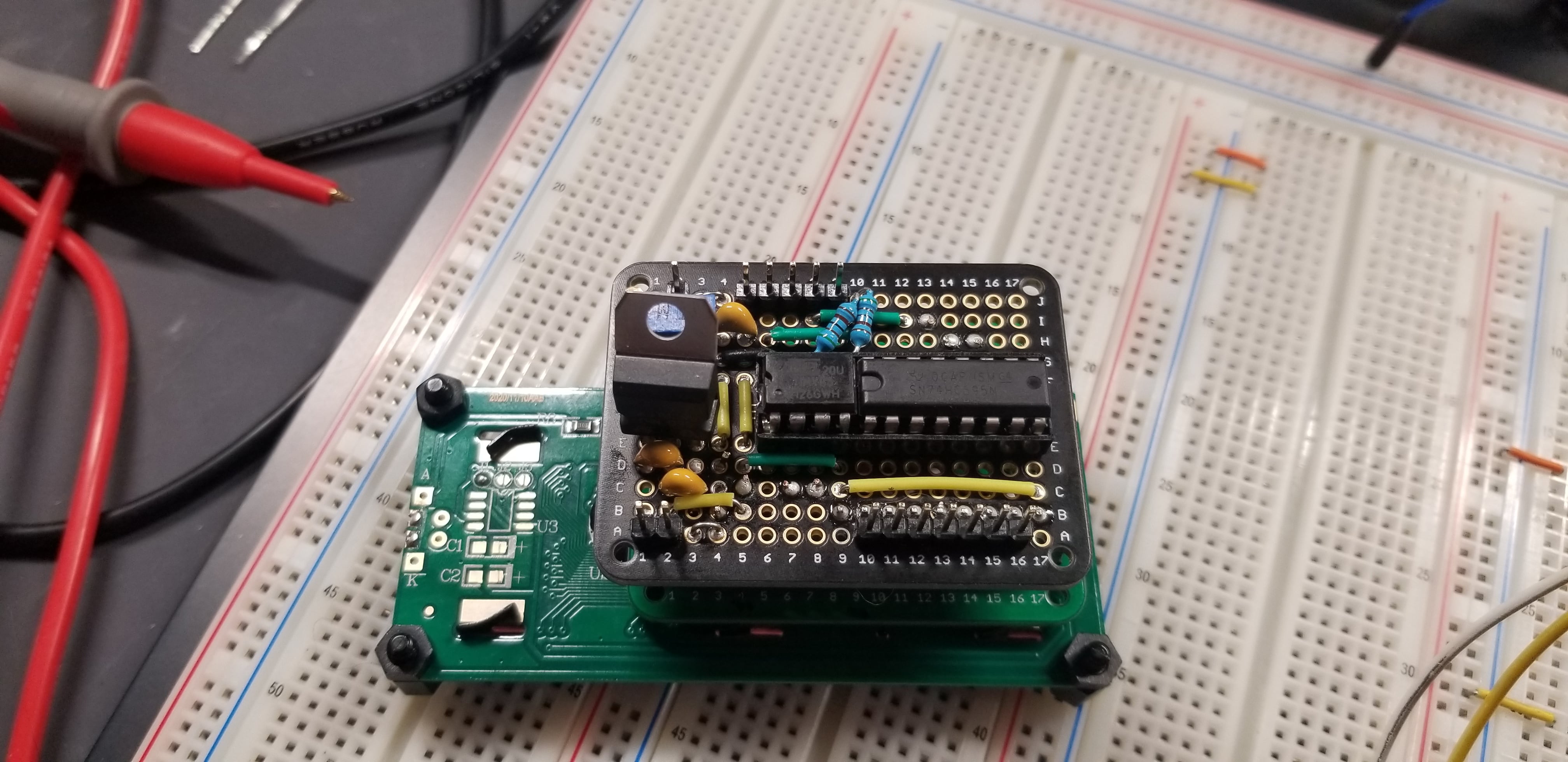
I was stubborn and wanted to use an attiny85 regardless of whether it was a good idea or not. 5 pins isn’t enough to control the display so I used a shift register as an IO expander to talk to the 1602 led display using SPI.
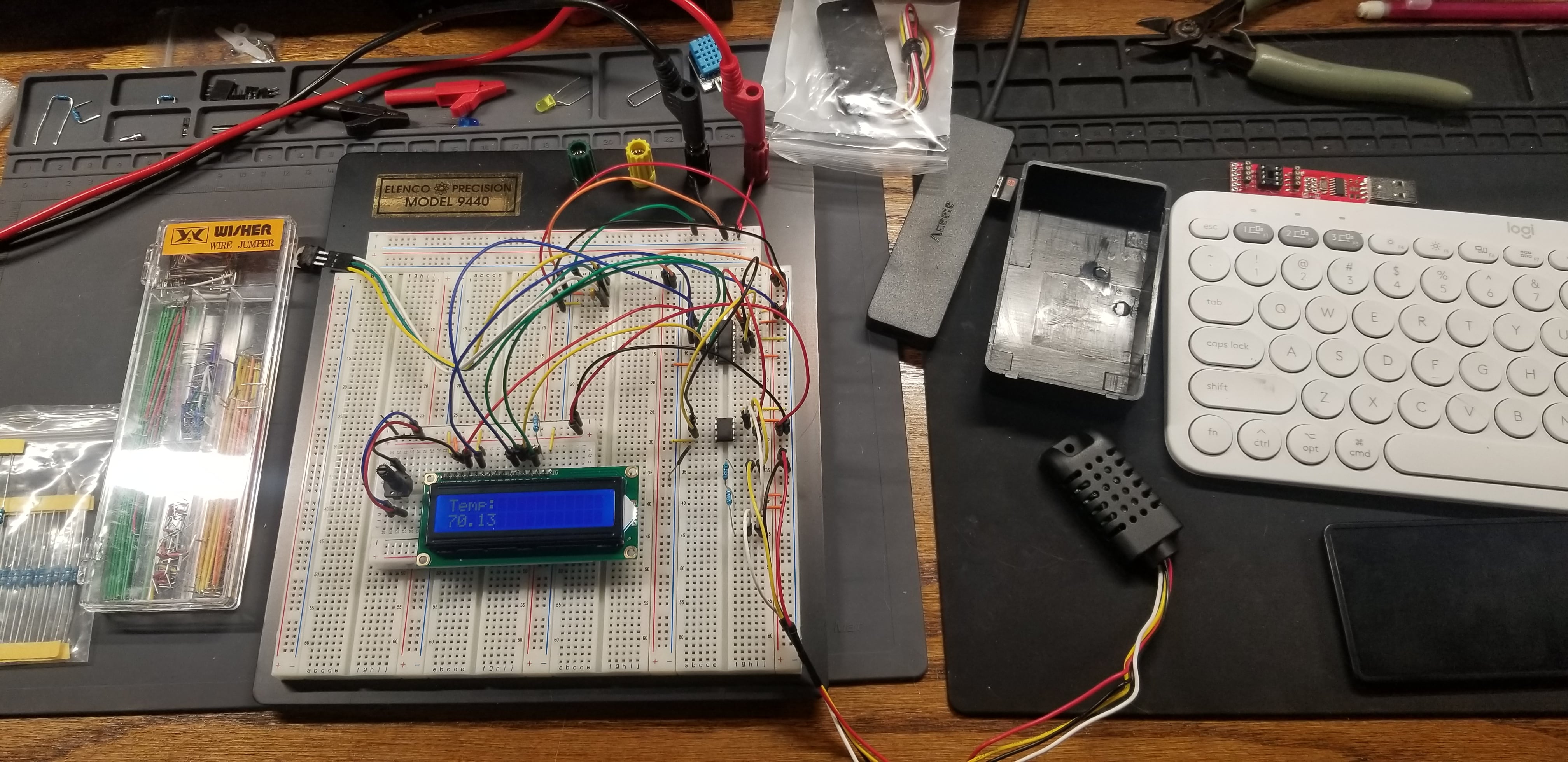
The temp/humidity sensor originally was an aht11 but apparently that unit is extremely sensitive to timing and I couldn’t quite get it right with the attiny. I switched to an AM2301B and that used i2c for communication and worked really well.
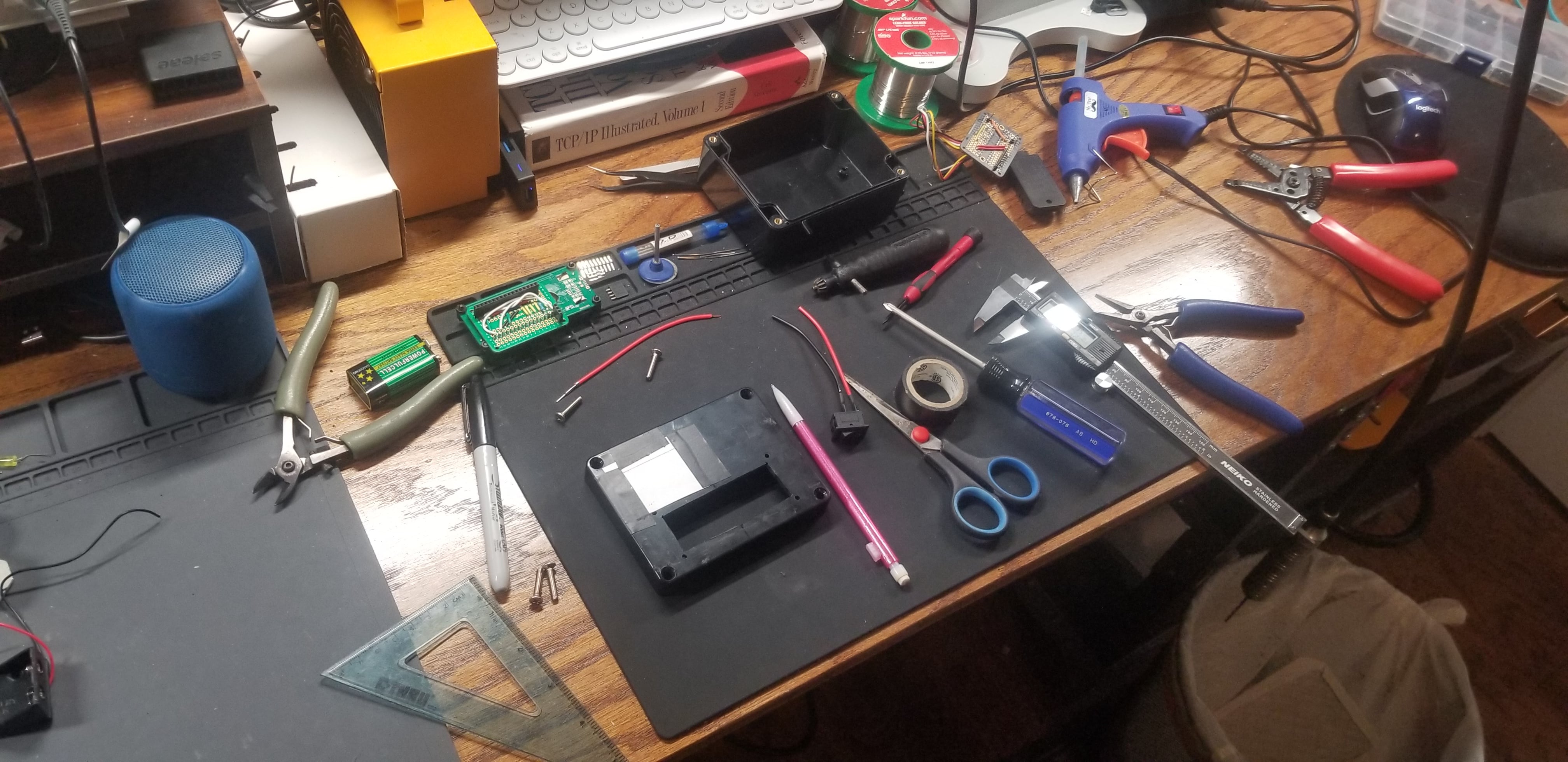
First try I soldered everything backwards but I eventually got it right.
The packing took forever and I ended up having to buy multiple project boxes to get the right size.
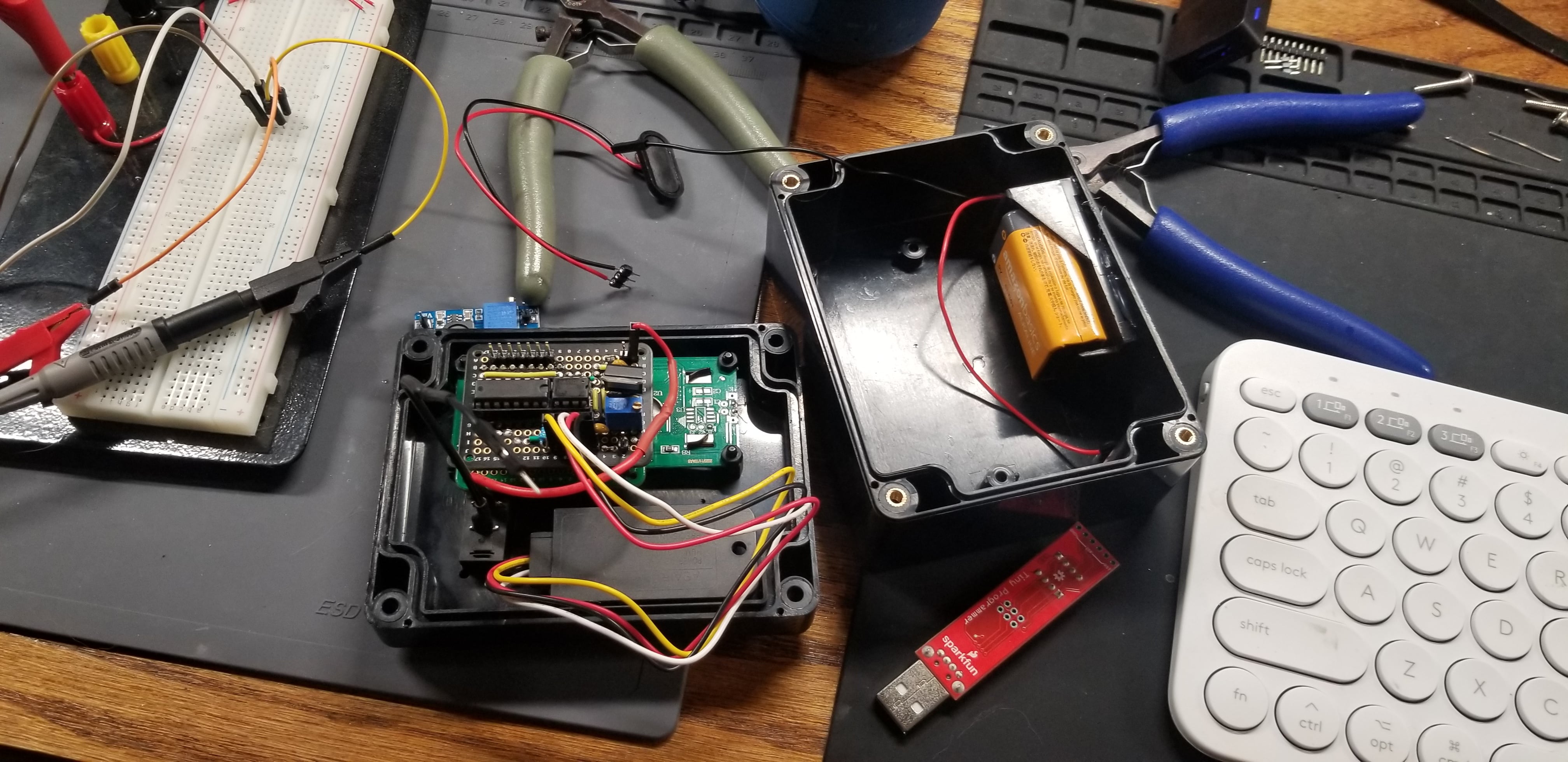
All done!

2022-07-15
7 Segment LED Counter
This was a funny project where I tried to build a simple 7 segment led counter without using a microcontroller. Each digit is controlled separately using 4026’s and a sub 15 ms clock controlling which led is displayed, targeting a digit using a mux. 15 ms was chosen because it’s faster than I could notice the counter changing, kinda like controlling led brightness using pwm. The counter ticks up based on a second slower clock or a button.
I isolated the clocks into separate modules using 555 timers, both of which took forever to solder. One was in a fixed astable mode, the other a toggle-able monostable button debouncer or a bi-stable latch.
Ran out of diodes on this one…

2022-07-10
Simple Oscillator

Probably the first circuit I tried to solder together. An astable oscillator that was so astable the timing was all over the place!